I purchased Smithy 1220XL Lathe/Mill/Drill a couple of years ago and began my machining career. I have no training nor instruction in any type of machining, and have never touched a lathe until I bought the Smithy. I also have recently purchased a couple of books on metal casting and have built a small furnace that I use to melt aluminum.
| Part | Material |
|---|---|
| Front Gear Cover | Cast aluminum |
| Crankcase | Cast aluminum |
| Crankshaft | 1.5" Stainless steel bar |
| Cam Shaft Cover | Cast aluminum |
| Cam Shaft | 0.5" drill rod |
| Pistons | 1.5" aluminum bar |
| Piston Rods | 3/8" aluminum plate |
| Rings | 1.25" drill rod |
| Valves and Keepers | 0.5" stainless steel bar |
| Valve seats | Brass rod |
| Cylinder Liners | 1" steel water pipe |
| Cylinders | cast aluminum |
| Cylinder Heads | cast aluminum |
| Rocker ArmSupports | aluminum plate |
| Rocker Arms | 1/4 inch steel plate |
| Push Rods | 1/8 inch aluminum tubing |
| Rear cover w/mount | cast aluminum |
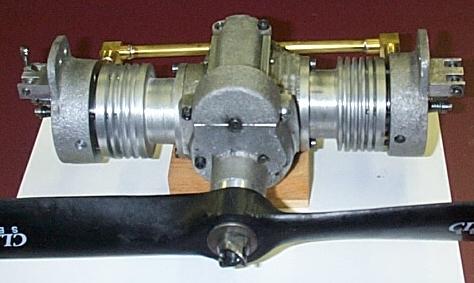
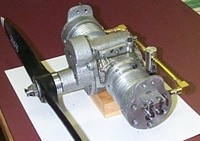
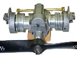
Many of the engine parts are made from cast aluminum, and are cast in my shop. To date I have the following parts (Shown in table on left). You can get the plans that I have drawn so far.
This page is no longer under construction
Last updated 11-25-00
These pages copyright (c) 2000
by Glen Bond
Send me Email
Feb. 1, 2000 updates
Feb. 13, 2000 updates
April 8, 2000 The new camshaft
September, 2000 Update --> The Verdict: Re-design it!